This is really one of the most informative videos i've seen in a while for this really confusing topic. Really well done by INE thanks for sharing this.

Setting MAC address to interface
switchport port-security mac abcd.abcd.abcd Violation modes : Protect : drops packets silently shutdown : shuts down the port (you can configure Err-disable recovery mechanism) errdisable recovery cause psecure-violation errdisable recovery interval 180 Restrict : generate snmp trap after dropping Aging MAC address entries : switchport port-security aging timeout <> switchport port-security aging type <aging/inactivity> *** For HSRP we can make interfaces use Use-BIA option to avoid virtual MAC to be used and securely blocked DHCP snooping : The idea is to avoid clients from sending DHCP offer and leases to other clients unless on trusted ports configuration : ip dhcp snooping ip dhcp snooping vlan 123 Needed on interface connected to DHCP server and trunk ports (case access switch) ip dhcp snooping trust To limit rate on an interface : ip dhcp snooping limit rate <pps> Option 82 when switch is configured with ip dhcp snooping it adds option 82 value and don't add "giaddr" value and by default cisco router configured as DHCP server when gets null "giaddr" it drops the request Workaround -Configure switch to neglect option 82 and consequently add "Giaddr" value "no ip dhcp snooping information option" or -Configure router DHCP server to accept DHCP requests with "Giaddr" value null"ip dhcp relay information trust-all" IF you want to configure option 82 parameters on switch "circuit ID - Remote-ID" interface fa0/1 ip dhcp snooping information option format-type circuit-id string ROUTER6 ip dhcp snooping information option format remote-id string SW1 ip dhcp snooping information option allow-untrusted (Allows switch to accept option 82 DHCP requests from untrusted ports) Static DHCP binding and saving database ip dhcp snooping binding 1234.1244.1244 vlan 123 123.123.123.123 interface gi0/1 expiry <> ip dhcp snooping database flash:/dhcp-bind.txt ip dhcp snooping database write-delay 15 <<<<<<< 15 seconds between database updating IP ARP inspection : (will use cisco doc on this) http://www.cisco.com/c/en/us/td/docs/switches/lan/catalyst3560/software/release/12-2_44_se/configuration/guide/scg/swdynarp.html I'm counting on this blog post to confirm my understanding because it could be quite misleading here.
BPDU Filter and BPDU Guard By Marko Milivojevic Below is my blog study self notes after reading this blog (so read the blog and ignore what's written below) Portfast (global) : enable port fast on all access ports conditionally and if a BPDU is received on one of those ports it transit to non port fast mode Portfast(interfcae) : enable port fast on all access ports conditionally BPDUfilter & BPDUGuard (global) : Must be accompanied by portfast - note for port filter if BPDU is received on interface it lose its portfast status and consequently lose its BPDUfilter feature BPDUfilter (interface) : unconditionally prevent send/receive of BPDU on interface I always hate timers , but anyway here are my few notes on spanning tree timers .... take care those timers are only valid for STP 802.1d as RSTP 802.1w is non timer based. Now for STP we have below timers as per Cisco :
For max-age it means that the switch will consider last BPDU it received valid for 20 seconds and it won't time out the BPDU except after 20 seconds ... so if a switch lose connectivity to the root switch there will be : 20 seconds to age out old BPDU info + 15 seconds Learning + 15 seconds Forwarding = 50 seconds lost Now for 802.1W which is rapid spanning tree , we no longer count on timers as 802.1w depends on exchanging BPDU as hello between switches. By default the rapid spanning tree times out after losing 3 consecutive BPDU's that's 6 seconds (it sends BPDU every 2 seconds) unless it's connected to 802.1D domain then those timers will be important. Now those timers in 802.1d needed to have some enhancements to it so below is the killing concept of backbone fast / uplink fast (quoted from http://www.dasblinkenlichten.com/spanning-tree-802-1d-timers-and-misc/) UplinkFast Just quick note cause i always forget this part , now how does OSPF calculate it's metric and what i mean by metric i mean when you issue the command (show ip route) what's this metric how did it get it ?
Cost = (10 Mgb/s / BW ) Rack1SW2#sh ip route 150.1.6.0 Routing entry for 150.1.6.0/24 Known via "ospf 1", distance 110, metric 63, type inter area Last update from 155.1.58.5 on Vlan58, 00:30:07 ago Routing Descriptor Blocks: * 155.1.58.5, from 150.1.5.5, 00:30:07 ago, via Vlan58 Route metric is 63, traffic share count is 1 Now we need to see who advertise this route , OSPF as INE explains works as both distance vector and link state at the same way , distance vector in a fashion that it deduce its metric for inter-area routes based on the metric advertised by the ABR , then it caclulates it's cost of reaching the ABR itself Rack1SW2#show ip ospf database summary 150.1.6.0 OSPF Router with ID (150.1.8.8) (Process ID 1) Summary Net Link States (Area 3) Routing Bit Set on this LSA LS age: 1798 Options: (No TOS-capability, DC, Upward) LS Type: Summary Links(Network) Link State ID: 150.1.6.0 (summary Network Number) Advertising Router: 150.1.5.5 <<<<<< ABR router LS Seq Number: 80000003 Checksum: 0x6B52 Length: 28 Network Mask: /24 TOS: 0 Metric: 62<<<<<<< Metric advertised by ABR Rack1SW2#show ip ospf int Vlan58 | i Cost Process ID 1, Router ID 150.1.8.8, Network Type BROADCAST, Cost: 1 Therefore we deduce total cost to be = 62 + 1 = 63 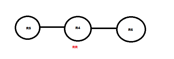
R5 (note we have MPLS running between 3 routers) ip vrf VA R4 ( route-reflector) router bgp 100 R6 ip vrf VA Below is the task required from INE Vol1 MPLS workbook the main aim was to establish Inter-Vrf routing without using MPLS ( well i used a BGP solution) which differs from the solution offered in INE book 
My idea was to test how can i exchange inter-vrf routing using BGP , INE made a tricky solution which is configuring R6 to exhange routes statically ip route vrf VPN_A 192.168.7.0 255.255.255.0 FastEthernet0/0.76 155.1.76.7 ! ip route vrf VPN_B 172.16.7.0 255.255.255.0 FastEthernet0/0.67 155.1.67.7 Note This trick only works if their is no recursive routing needed (i.e) next hop appears as connected So here's below my Solution without the need to R6 and only using BGP vpnv4 ip vrf VA LSR's running LDP discover each others using Hello messages , then establish a session using a TCP connection ip cef mpls ldp router-id Lo0 force (force indicates to immediately re-establish session using the Lo0 IP) int fa0/0 mpls ip LDP hello messages are multicast using 224.0.0.2 UDP 646, including hello interval and hold time if hold time expires session is torn down (default 5 , 15) LDP ID : routerid:0 or 1 ... 1 for atm perinterface label space which is not in the exam , so it'll always appear as IP:0 ** Note if the neighbor don't have a route for the router-id IP in it's routing table the session will never form Below are excerpts i need from MPLS Fundamentals Chapter 4 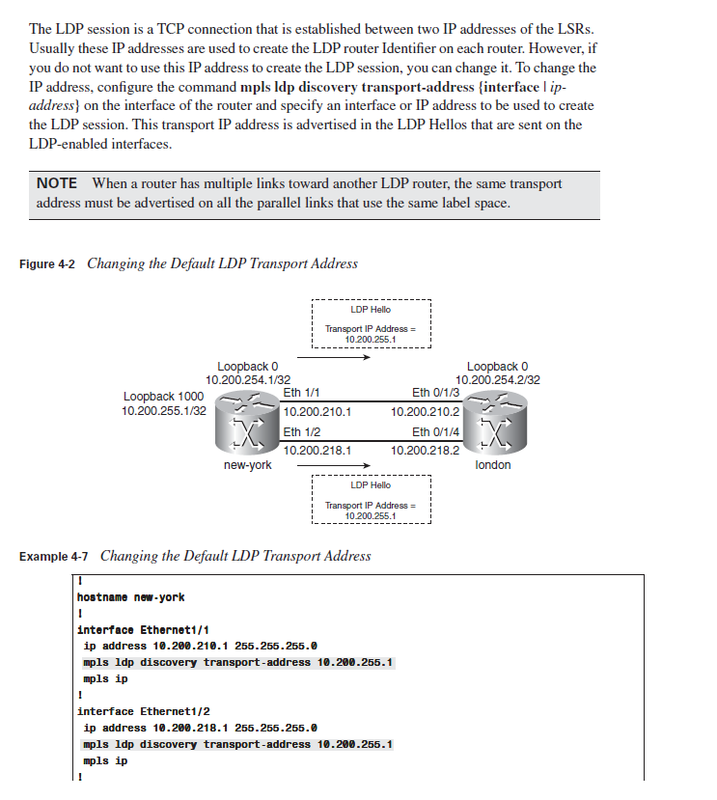 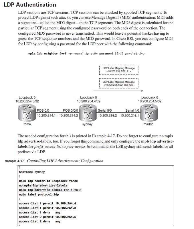 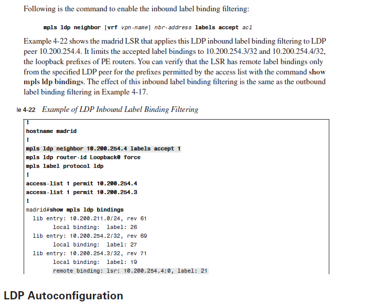 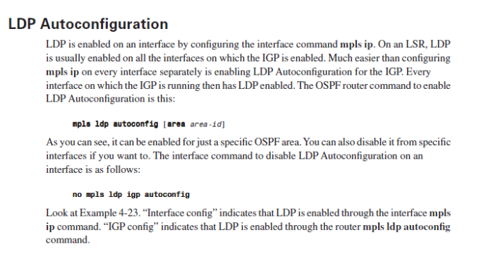 - Inactive for 15 seconds ages out netflow - Create and update netflow cache , then export them to collector use UDP or SCTP - Aggregate if configured Pre processing Packet sampling : statistical sampling Filtering : status for specific network To be exported : 15 seconds default inactivity 30 minutes export Active Netcache is full it exports them to server TCP RST & FIN Flag seen (we don't export data to collector until flow expires) Aggregation scheme (how you want to aggregate data) Netflow versions for export --------- 5 include BGP AS information 7 only supported on catalyst 8 added aggregation 9 it is flexible and use templates 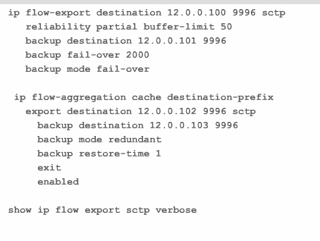
SCTP use TCP more relible 
debug ip flow export debug ip flow cache ip flow-capture icmp ip flow-capture mac-add ip flow capture ttl ip flow-capture vlan-id ip flow-cache entries 1024 ip flow-cache timeout active 15 ip flow-cache timeout inactive 30 (seconds) ip flow-export destination 12.0.0.2 port 9996 ip flow-export version 9 (enable netflow) int fa0/0.23 ip flow in ip flow eg (if we ping R1 to R3) we get recorded ping on interface show ip flow interface (show ip flow enabled interfaces) show ip flow export template (show you timers) (traffic sourced from router don't enter cache flow table) * means egress traffic Ip flow-top-talkers top 10 sort-by packets match protocol 1 show ip flow top-talkers Aggregation configuration ---------------------- ip flow-aggregation cache destination-prefix export destination 12.0.0.100 9996 export ver 9 cache entries 1024 show ip cache flow aggregation destination-prefi Flow-sampler ==== flow-sampler-map MED-SAMP mode random one-out-of 10 int fa0/0.12 flow-sampler MED-SAMP egress *** Now if you apply it on interface this makes it when you do show ip cache-flow 10% less traffic we can use policy-map policy-map NETflowMAP class class-default netflow-sampler MED-SAMP int fa0/0.12 service policyu-out 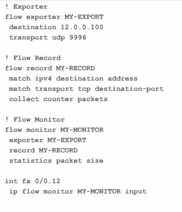
Verification for flow-monitor
=== show flow monitor MY-MONITOR show run flow show flow interface show flow expo Traffic Export
12.4t - Features guide - (search traffic export) KRON Cisco IOS Software Releases 12.4 T ---> Network Management Configuration Guide ---> Cisco Networking Services Configuration Guide (search KRON) RCMD ( Remote command ) Cisco IOS Software Releases 12.4 T ---> Cisco IOS Configuration Fundamentals Configuration Guide ----> Part 6 Configuring Basic File Transfer --> (search RCMD) | 
The posts in this blog are not a technical reference it's just my humble way of understanding topics in my CCIE pursuit , they could be right and could be wrong and most importantly they're debatable.
Note All comic pictures used on this blog are made using the amazing Facebook app bitstrips

AuthorDuring the past few years I've worked on becoming a networks expert , with more than 3 years of practical experience within Orange Business Services , i started to hold grip of important technical aspects to the complex network design specially with Cisco networks. ArchivesCategories |
 RSS Feed