I always had this trouble of understanding how OSPF converge and how its timers really work , it's been always a topic that bother me. This blog post is not mine and most of its content is from this awesome blog post by Petr labrukhov on INE am just trying to summarize key points in this blog post for me to remember them whenever i need to. Again if you want to learn about timers it's better to leave here and go there : http://blog.ine.com/2009/12/31/tuning-ospf-performance/OSPF Cost is simple as simple is
Interface cost is derived from the bandwidth. Formula is:
Cost = Reference / Bandwidth.
By default, Reference is 100000 [ Kb/s ].
So, for your bandwidth of 5120, cost should be:
Cost = 100000 / 5120 = 19.53. Rounded down to the closest integer, it's 19.
Incremental SPF
Most important when a new node is added it use distance vector
to converge and not run SPF all over again
LSA group pacing
LSA age : Time to consider LSA no longer valid
LSA checksum : Checking LSA checksum to make sure non of LSA's is corrupted
by default LSA max age is 1 hour , re-flood LSA every 30 mins, after 1 hour remove LSA
periodic checksum on LSA's to make sure that they're ok
How ?
Originally refresh every 30 mins and referesh all self LSA no matter how old,this would result in CPU spikes
Every 10 mins run periodic check sum on all LSA and flush any aged one
Enhancement :
An IOS scan checks the LSA that are close to their half-life time 30 mins were refresshed not all LSA's ! problem is still every 30 mins we'll see some spikes
Group Pacing
When an LSA reach its half-life time the router waits for an interval to see if any LSA also will reach its half life-time "pacing interval" default 240 seconds then router groups similar life time LSA's and referesh them
We can do same process of grouping LSA's that are close to aging out and also group them together
Command:
timers pacing
- Flood : ospff flood pacing timer
- lsa-group : ospf lsa group pacing timer
- retransmission : ospf retransmision pacing timer
Rack1R5#show ip ospf | inc transmission|pacing
LSA group pacing timer 240 secs <<<<< For LSA refresh/aging
Interface flood pacing timer 33 msecs <<<<< Interface flood list (LSA) to hold updates and wait for more
Retransmission pacing timer 66 msecs <<<<< Un-ack to group unack together SPF & LSA throttling
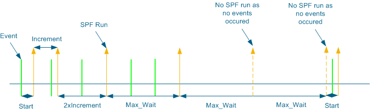
- When an event occurs don't respond to it imediatly by generating LSA's or running SPF but wait some time hoping to accumulate more events
Cisco implements an exponential backoff timer
timers throttle spf start increment max-wai
when an event happen use the start timer if another event happen use increment to increment the timer you used, then until you reach max-wait if 2 max-wait time passes with no events reset the process timers
So it's always been my worst topic of the day , understanding what those values are. Even in live network at work i always use their default values and never tried to modify them, but here i am today and it took me quite a while to try to somehow understand how those work and below is my simple simplification of the concept which may or may not be correct.
The first way to understand those values is to divide the technologies that use those terms :
1- Traffic Shaping
2- Frame-Relay Traffic Shaping
3- Policing
4- CAR
Each of those technologies use those terms BC,BE but each technology use those terms differently. Snapshot from Jeremy Cioara Explanation of shaping 1-Traffic Shaping
What's traffic shaping , what traffic shaping does is that it tries to buffer excess packets and maintain a constant traffic rate that's below the customer rate. This is mostly seen on Metroethernet connections for example where the Ethernet speed is 10 Mgb/s and customer only purchased 5 Mgb/s so the only way to stop him is to use traffic shaping under a policy-map
which would be something like this.
policy-map limit-out
class class-default
shape average 1000000
now what if the customer can burst more than this rate we need to set two values one Bc which is the bytes rate (or in other words the Tc) of the customer and the AIR which is the maximum allowed rate that the customer can send traffic in.
Let's say that the customer AIR would be 8 Mg in this case we would need to do the math.
AIR = (bc+be)/Tc ok but what are the Tc and the Bc
so the point here the Bc is just a translation to tell the router what's its Tc to shape upon and to do the math in case we need to calculate the Be
For example by default R5(config)#policy-map LIMIT
R5(config-pmap)# class class-default
R5(config-pmap-c)#shape average 1000000
R5#show policy-map int fa1/0 out
FastEthernet1/0
Service-policy output: LIMIT
Class-map: class-default (match-any)
112858 packets, 157474318 bytes
30 second offered rate 6612000 bps, drop rate 6505000 bps
Match: any
Traffic Shaping
Target/Average Byte Sustain Excess Interval Increment
Rate Limit bits/int bits/int (ms) (bytes)
1000000/1000000 6250 25000 25000 25 3125 <<<<<<<<<<<< The router use default interval 25 ms
Adapt Queue Packets Bytes Packets Bytes Shaping
Active Depth Delayed Delayed Active
- 0 1961 2682860 1157 1606954 no
Now if we want to modify those parameters
R5(config)#policy-map LIMIT
R5(config-pmap)#class class-default
R5(config-pmap-c)#shape average 1000000 1000000 1000000
R5#show policy-map int fa1/0 out
FastEthernet1/0
Service-policy output: LIMIT
Class-map: class-default (match-any)
112852 packets, 157473902 bytes
30 second offered rate 12973000 bps, drop rate 12763000 bps
Match: any
Traffic Shaping
Target/Average Byte Sustain Excess Interval Increment
Rate Limit bits/int bits/int (ms) (bytes)
1000000/1000000 250000 1000000 1000000 1000 125000 <<<<<<<<< The router re-adjust its Tc calculations
Adapt Queue Packets Bytes Packets Bytes Shaping
Active Depth Delayed Delayed Active
- 0 1955 2682444 1157 1606954 no
Cisco recommends not messing around with those values as i just did :)
Important note here Bc,BE are valued in bits 2- Frame Relay Traffic-Shaping
Here the shaping mechanism is nearly the same as previously explained shaping commands except for the fact that the Bc,Be values are defined under the frame-relay map class. and the map-class can be configured under a specific DLCI.
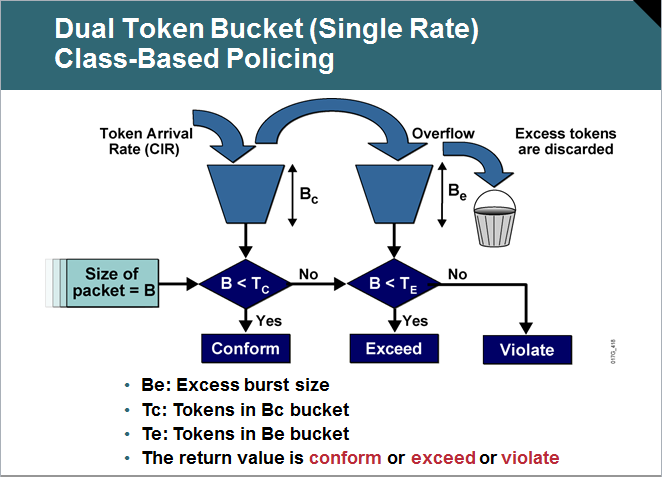
3-,4 Policing & CAR Here one of the major differences is that Bc,Be values are expressed in Bytes and here the Bc,Be are a way of expressing excess bytes to policing and not bits to traffic shaping. In most of examples i saw in policing we assume the Tc to be 1 second.
So Bc here refers to the bytes that i can burst to conform with the policing policy.
For example :
police cir 96000 bc 12000 be 6000 conform transmit exceed set-dscp-trans 0 violate-action drop
Here the Tc = 1 since Bc = 960000/8 and we can burst up to 0.5's second worth of traffic and that's because
be = 6000 byte
so bc,be here express the excess bytes limit and the amount of byte they can exceed This post is not final i believe this can be considered a first draft to my long struggle with Bc,Be values :)
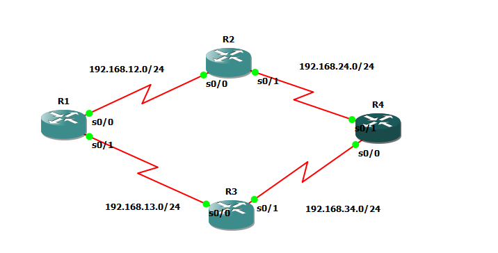
I've been facing troubles with redistribution lately specially on big scale labs , and i found the best blog post about it is the INE blog posts by Petr Lapukhov http://blog.ine.com/2008/02/09/understanding-redistribution-part-i/ http://blog.ine.com/2008/02/19/understanding-redistribution-part-ii/ http://blog.ine.com/2008/03/17/understanding-redistribution-part-iii/ So i created the generic lab on GNS3 and will start working on it now IOS used : c3640-ik9o3s-mz.124-7
Using passive interface on RIP only does 1 thing (stop sending RIP updates out of interface) but will not stop advertising the subnetwork on the interface to peer neighbors
Ex On R2 enabling passive interface on S0/0 R2(config)#router rip
R2(config-router)#passive-interface s0/0
If you check on R1 now you'll see that 2.2.2.2 is no longer learnt from R2 R1#sh ip route 2.2.2.2
Routing entry for 2.2.2.2/32
Known via "rip", distance 120, metric 3
Redistributing via rip
Last update from 192.168.13.3 on Serial0/1, 00:00:20 ago
Routing Descriptor Blocks:
* 192.168.13.3, from 192.168.13.3, 00:00:20 ago, via Serial0/1 <<<<<<< R3
Route metric is 3, traffic share count is 1
Ex2: Enabling passive interface on loopback interface , long ago i used to believe would stop router processor from sending the RIP update about this network but turned out I'm wrong R2(config)#router rip
R2(config-router)#passive-interface lo0
R4#sh ip route 2.2.2.2
Routing entry for 2.2.2.2/32
Known via "rip", distance 120, metric 1
Redistributing via rip
Last update from 192.168.24.2 on Serial0/1, 00:00:22 ago
Routing Descriptor Blocks:
* 192.168.24.2, from 192.168.24.2, 00:00:22 ago, via Serial0/1 <<<<< Still R4 learns about it
Route metric is 1, traffic share count is 1
So seems to do filtering we can use route-filtering but not passive interface :(
Summerization in Ripv2 is made using interface level configuration.
There are 2 notes that i want to point out down there , first while doing this lab i actually made a loop
second i want to point out to one limitation in RIPv2 concerning summerization
Task 1 : Summerize 2.0.0.0/8 out of R2 to R1 instead of 2.2.2.2/32 R2(config-if)#ip summary-address rip 2.0.0.0 255.0.0.0
Looks beautiful but now take another look at our topology ? don't you notice a problem , the problem is that the summary route kept appearing and disappearing from R1 so i made a debug ip rip database and noticed the below *Mar 1 00:42:49.187: RIP-DB: Remove 2.0.0.0/8, (metric 4294967295) via 192.168.12.2, Serial0/0
What happened is the following R2 advertise to R1 2.0.0.0/8 so R1 advertise it to R3 then R4 and R4 then advertise it back to R2 from R2 momentery
R 2.0.0.0/8 [120/4] via 192.168.24.4, 00:00:00, Serial0/1
Note* that R2 don't install summary entry once summerization is configured and seems that this is what cause the problem
Solution Make R2 summarize out of all interfaces not only S0/0 but also through S0/1 to avoid loop
Task 2 : Summarize network 192.168.0.0/16 out of S0/0
R2(config-if)#ip summary-address r 192.168.0.0 255.255.0.0
Summary mask must be greater or equal to major net
It turned out that RIP doesn't support superneting so i can't advertise a summary address of a super net like 192.168.0.0 since it's by default a class C of /24
The only solution to fix issue would be create a null 0 route and resdistribute it into RIP
R2(config)# ip route 192.168.0.0 255.255.0.0 null 0
R2(config)# router rip
R2(config-router)# redistribute static
R1#sh ip route | i /16
R 192.168.0.0/16 [120/1] via 192.168.12.2, 00:00:04, Serial0/0
When RIP v2 authentication is enabled on 1 router it means it'll authenticate the updates coming from peer and not the updates being sent to peer.
Example here enabling authentication only on R2 R2#sh run int s0/0
Building configuration...
Current configuration : 193 bytes
!
interface Serial0/0
ip address 192.168.12.2 255.255.255.0
ip rip authentication mode md5
ip rip authentication key-chain cisco
Results of debug
*Mar 1 00:10:26.535: RIP: ignored v2 packet from 192.168.12.1 (invalid authentication)
But if we check routing table on R1 and R2 R1#sh ip route 2.2.2.2
Routing entry for 2.2.2.2/32
Known via "rip", distance 120, metric 1
Redistributing via rip
Last update from 192.168.12.2 on Serial0/0, 00:00:01 ago
Routing Descriptor Blocks:
* 192.168.12.2, from 192.168.12.2, 00:00:01 ago, via Serial0/0
Route metric is 1, traffic share count is 1
Router 1 still learns about routes from R2
But router 2 doesn't learn any routes from R1
R2#sh ip route 1.1.1.1
Routing entry for 1.1.1.1/32
Known via "rip", distance 120, metric 3
Redistributing via rip
Last update from 192.168.24.4 on Serial0/1, 00:00:21 ago
Routing Descriptor Blocks:
* 192.168.24.4, from 192.168.24.4, 00:00:21 ago, via Serial0/1 <<<<<<< From R4
Route metric is 3, traffic share count is 1
Noting that i rescheduled my exam , i had to make an analysis to where i stand. So i used the blueprint topics as usual to analyze my current status using the traffic light pattern. Red-Yellow-Green
The topics in Red will get my focus and most probably will be making dedicated blog posts for them to stick them in my head. Exam Sections and Sub-task Objectives
1.00 Implement Layer 2 Technologies √
1.10 Implement Spanning Tree Protocol (STP)
(a) 802.1d
(b) 802.1w
(c) 801.1s
(d) Loop guard
(e) Root guard
(f) Bridge protocol data unit (BPDU) guard
(g) Storm control
(h) Unicast flooding
(i) Port roles, failure propagation, and loop guard operation
1.20 Implement VLAN and VLAN Trunking Protocol (VTP)
1.30 Implement trunk and trunk protocols, EtherChannel, and load-balance
1.40 Implement Ethernet technologies
(a) Speed and duplex
(b) Ethernet, Fast Ethernet, and Gigabit Ethernet
(c) PPP over Ethernet (PPPoE)
1.50 Implement Switched Port Analyzer (SPAN), Remote Switched Port Analyzer (RSPAN), and flow control
1.60 Implement Frame Relay
(a) Local Management Interface (LMI)
(b) Traffic shaping
(c) Full mesh
(d) Hub and spoke
(e) Discard eligible (DE)
1.70 Implement High-Level Data Link Control (HDLC) and PPP
2.00 Implement IPv4
2.10 Implement IP version 4 (IPv4) addressing, subnetting, and variable-length subnet masking (VLSM)
2.20 Implement IPv4 tunneling and Generic Routing Encapsulation (GRE)
2.30 Implement IPv4 RIP version 2 (RIPv2)
2.40 Implement IPv4 Open Shortest Path First (OSPF)
(a) Standard OSPF areas
(b) Stub area
(c) Totally stubby area
(d) Not-so-stubby-area (NSSA)
(e) Totally NSSA
(f) Link-state advertisement (LSA) types
(g) Adjacency on a point-to-point and on a multi-access network
(h) OSPF graceful restart
2.50 Implement IPv4 Enhanced Interior Gateway Routing Protocol (EIGRP)
(a) Best path
(b) Loop-free paths
(c) EIGRP operations when alternate loop-free paths are available, and when they are not available
(d) EIGRP queries
(e) Manual summarization and autosummarization
(f) EIGRP stubs
2.60 Implement IPv4 Border Gateway Protocol (BGP)
(a) Next hop
(b) Peering
(c) Internal Border Gateway Protocol (IBGP) and External Border Gateway Protocol (EBGP)
2.70 Implement policy routing
2.80 Implement Performance Routing (PfR) and Cisco Optimized Edge Routing (OER)
2.90 Implement filtering, route redistribution, summarization, synchronization, attributes, and other advanced
features
3.00 Implement IPv6
3.10 Implement IP version 6 (IPv6) addressing and different addressing types
3.20 Implement IPv6 neighbor discovery
3.30 Implement basic IPv6 functionality protocols
3.40 Implement tunneling techniques
3.50 Implement OSPF version 3 (OSPFv3)
3.60 Implement EIGRP version 6 (EIGRPv6)
3.70 Implement filtering and route redistribution
4.00 Implement MPLS Layer 3 VPNs
4.10 Implement Multiprotocol Label Switching (MPLS)
4.20 Implement Layer 3 virtual private networks (VPNs) on provider edge (PE), provider (P), and customer
edge (CE) routers
4.30 Implement virtual routing and forwarding (VRF) and Multi-VRF Customer Edge (VRF-Lite)
5.00 Implement IP Multicast
5.10 Implement Protocol Independent Multicast (PIM) sparse mode
5.20 Implement Multicast Source Discovery Protocol (MSDP)
5.30 Implement interdomain multicast routing
5.40 Implement PIM Auto-Rendezvous Point (Auto-RP), unicast rendezvous point (RP), and bootstrap router
(BSR)
5.50 Implement multicast tools, features, and source-specific multicast
5.60 Implement IPv6 multicast, PIM, and related multicast protocols, such as Multicast Listener Discovery
(MLD)
6.00 Implement Network Security
6.01 Implement access lists
6.02 Implement Zone Based Firewall
6.03 Implement Unicast Reverse Path Forwarding (uRPF)
6.04 Implement IP Source Guard
6.05 Implement authentication, authorization, and accounting (AAA) (configuring the AAA server is not
required, only the client-side (IOS) is configured)
6.06 Implement Control Plane Policing (CoPP)
6.07 Implement Cisco IOS Firewall
6.08 Implement Cisco IOS Intrusion Prevention System (IPS)
6.09 Implement Secure Shell (SSH)
6.10 Implement 802.1x
6.11 Implement NAT
6.12 Implement routing protocol authentication
6.13 Implement device access control
6.14 Implement security features
7.00 Implement Network Services
7.10 Implement Hot Standby Router Protocol (HSRP)
7.20 Implement Gateway Load Balancing Protocol (GLBP)
7.30 Implement Virtual Router Redundancy Protocol (VRRP)
7.40 Implement Network Time Protocol (NTP)
7.50 Implement DHCP
7.60 Implement Web Cache Communication Protocol (WCCP)
8.00 Implement Quality of Service (QoS)
8.10 Implement Modular QoS CLI (MQC)
(a) Network-Based Application Recognition (NBAR)
(b) Class-based weighted fair queuing (CBWFQ), modified deficit round robin (MDRR), and low latency
queuing (LLQ)
(c) Classification
(d) Policing
(e) Shaping
(f) Marking
(g) Weighted random early detection (WRED) and random early detection (RED)
(h) Compression
8.20 Implement Layer 2 QoS: weighted round robin (WRR), shaped round robin (SRR), and policies
8.30 Implement link fragmentation and interleaving (LFI) for Frame Relay
8.40 Implement generic traffic shaping
8.50 Implement Resource Reservation Protocol (RSVP)
8.60 Implement Cisco AutoQoS
9.00 Troubleshoot a Network
9.10 Troubleshoot complex Layer 2 network issues
9.20 Troubleshoot complex Layer 3 network issues
9.30 Troubleshoot a network in response to application problems
9.40 Troubleshoot network services
9.50 Troubleshoot network security
10.00 Optimize the Network
10.01 Implement syslog and local logging
10.02 Implement IP Service Level Agreement SLA
10.03 Implement NetFlow
10.04 Implement SPAN, RSPAN, and router IP traffic export (RITE)
10.05 Implement Simple Network Management Protocol (SNMP)
10.06 Implement Cisco IOS Embedded Event Manager (EEM)
10.07 Implement Remote Monitoring (RMON)
10.08 Implement FTP
10.09 Implement TFTP
10.10 Implement TFTP server on router
10.11 Implement Secure Copy Protocol (SCP)
10.12 Implement HTTP and HTTPS
10.13 Implement Telnet
I am now able to understand the key concepts of configuration but i absolutely have no idea how that thing works when it comes when doing this on the lab, so here's a quick small notes to what i understand right now. Taking the INE vol1 output from OER master configuration. ip prefix-list NET112 permit 112.0.0.0/24
!
oer-map OER 10 <<<<<<< OER MAP is the perfect way to make seperate policy rules for seperate traffic classes
match ip address prefix-list NET112
!
oer master
policy-rules OER
oer-map 10
set mode route observe <<<<<<<<<<<<<<< This means that traffic with for destination 112.0.0.0/24 will inherit default policy settings as it is but its mode route will be observe (i.e it won''t manipulate routing table)
!
oer master
mode route control
mode route metric static tag 1000 <<<<<< Setting static and BGP parameters for mainpulated routes injected to modify traffic path
mode route metric bgp local-pref 6000
active-probe tcp-conn 150.1.1.1 target-port 23
active-probe tcp-conn 150.1.4.4 target-port 23 <<<<<<< Instead of passivly collecting results send active probes using port 23 (note ip sla responder and reciever must accept those probes)
active-probe tcp-conn 150.1.6.6 target-port 23
!
learn
throughput <<<<<<<< learn throughput (number of bytes sent) & delay
delay
protocol tcp port 80 src <<<<<<<<<< Don't monitor all traffic classes but ONLY those protocols being matched will be monitored
protocol 1
protocol udp port range 16384 32767 src
periodic-interval 5 <<<<<<<<<<<<<<<<< Set them to 1 and 0 which is time it takes to learn and time it takes to sleep
monitor-period 3
aggregation-type bgp <<<<<<<<<<<<<<<<< Aggregate prefixes learnt to BGP prefixes (i.e if bgp entry is /32 the learnt prefic will be /32)
border 150.1.3.3 key-chain OER
interface Serial1/2 external
max-xmit-utilization percentage 80 <<<<<<<< max utilization is 75% by default we make it here 80
!
!
delay threshold 200 <<<<<< Threshold for delay is 200 ms
loss relative 30 <<<<<<<<<< Threshold for packet loss is 30 % this will trigger OER to search for an aternate pass
holddown 600 <<<<<<< If you make a decision hold it down for 600 seconds
mode select-exit best <<<<<<< By defailt its good , best means it will search for all possible alternatives and choose the best one
periodic 90
resolve utilization priority 1 variance 15
resolve delay priority 2 variance
This is absolutely not a technical post and not related to it , it's just my humble understanding of the concept in order for me to revise it anytime without needing to go through all the videos and the tutorials.
ahhh Where should we start if this is the first time you read about PFR/OER i do really recommend you want those 2 videos by Brian Denis they're the only available online from a 6 lectures series about PFR/OER i believe those 2 are fair enough to hold grip of the key concepts to PFR/OER Now after you watched the videos , i believe there's nothing you could do here what you could do is go to your GNS3 lab and start doing what you do best non stop hours of lab there are just few points that took me quite sometime to understand. (to be continued)
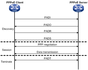
I had 1 hour and 20 minutes wasted trying to figure out the problem with my configuration and it turned out to be that for DHCP request to work the ip address must be on the virtual-template else how would the router know which DHCP pool it'd assign to the client.
Server config
interface Virtual-Template1
ip address 155.1.35.1 255.255.255.0
no peer default ip address
ppp authentication chap
bba-group pppoe 1
virtual-template 1
interface FastEthernet0/1.54
encapsulation dot1Q 54
pppoe enable group 1
ip dhcp pool 1
network 155.1.35.0 255.255.255.0
username R3 password 0 CISCO
Client Config
interface Dialer1
ip address dhcp
encapsulation ppp
dialer pool 1
ppp chap hostname R3
ppp chap password 0 CISCO
!
interface FastEthernet0/1
no ip address
duplex auto
speed auto
pppoe enable group global
pppoe-client dial-pool-number 1
|


 RSS Feed