When RIP v2 authentication is enabled on 1 router it means it'll authenticate the updates coming from peer and not the updates being sent to peer.
Example here enabling authentication only on R2 R2#sh run int s0/0
Building configuration...
Current configuration : 193 bytes
!
interface Serial0/0
ip address 192.168.12.2 255.255.255.0
ip rip authentication mode md5
ip rip authentication key-chain cisco
Results of debug
*Mar 1 00:10:26.535: RIP: ignored v2 packet from 192.168.12.1 (invalid authentication)
But if we check routing table on R1 and R2 R1#sh ip route 2.2.2.2
Routing entry for 2.2.2.2/32
Known via "rip", distance 120, metric 1
Redistributing via rip
Last update from 192.168.12.2 on Serial0/0, 00:00:01 ago
Routing Descriptor Blocks:
* 192.168.12.2, from 192.168.12.2, 00:00:01 ago, via Serial0/0
Route metric is 1, traffic share count is 1
Router 1 still learns about routes from R2
But router 2 doesn't learn any routes from R1
R2#sh ip route 1.1.1.1
Routing entry for 1.1.1.1/32
Known via "rip", distance 120, metric 3
Redistributing via rip
Last update from 192.168.24.4 on Serial0/1, 00:00:21 ago
Routing Descriptor Blocks:
* 192.168.24.4, from 192.168.24.4, 00:00:21 ago, via Serial0/1 <<<<<<< From R4
Route metric is 3, traffic share count is 1
Noting that i rescheduled my exam , i had to make an analysis to where i stand. So i used the blueprint topics as usual to analyze my current status using the traffic light pattern. Red-Yellow-Green
The topics in Red will get my focus and most probably will be making dedicated blog posts for them to stick them in my head. Exam Sections and Sub-task Objectives
1.00 Implement Layer 2 Technologies √
1.10 Implement Spanning Tree Protocol (STP)
(a) 802.1d
(b) 802.1w
(c) 801.1s
(d) Loop guard
(e) Root guard
(f) Bridge protocol data unit (BPDU) guard
(g) Storm control
(h) Unicast flooding
(i) Port roles, failure propagation, and loop guard operation
1.20 Implement VLAN and VLAN Trunking Protocol (VTP)
1.30 Implement trunk and trunk protocols, EtherChannel, and load-balance
1.40 Implement Ethernet technologies
(a) Speed and duplex
(b) Ethernet, Fast Ethernet, and Gigabit Ethernet
(c) PPP over Ethernet (PPPoE)
1.50 Implement Switched Port Analyzer (SPAN), Remote Switched Port Analyzer (RSPAN), and flow control
1.60 Implement Frame Relay
(a) Local Management Interface (LMI)
(b) Traffic shaping
(c) Full mesh
(d) Hub and spoke
(e) Discard eligible (DE)
1.70 Implement High-Level Data Link Control (HDLC) and PPP
2.00 Implement IPv4
2.10 Implement IP version 4 (IPv4) addressing, subnetting, and variable-length subnet masking (VLSM)
2.20 Implement IPv4 tunneling and Generic Routing Encapsulation (GRE)
2.30 Implement IPv4 RIP version 2 (RIPv2)
2.40 Implement IPv4 Open Shortest Path First (OSPF)
(a) Standard OSPF areas
(b) Stub area
(c) Totally stubby area
(d) Not-so-stubby-area (NSSA)
(e) Totally NSSA
(f) Link-state advertisement (LSA) types
(g) Adjacency on a point-to-point and on a multi-access network
(h) OSPF graceful restart
2.50 Implement IPv4 Enhanced Interior Gateway Routing Protocol (EIGRP)
(a) Best path
(b) Loop-free paths
(c) EIGRP operations when alternate loop-free paths are available, and when they are not available
(d) EIGRP queries
(e) Manual summarization and autosummarization
(f) EIGRP stubs
2.60 Implement IPv4 Border Gateway Protocol (BGP)
(a) Next hop
(b) Peering
(c) Internal Border Gateway Protocol (IBGP) and External Border Gateway Protocol (EBGP)
2.70 Implement policy routing
2.80 Implement Performance Routing (PfR) and Cisco Optimized Edge Routing (OER)
2.90 Implement filtering, route redistribution, summarization, synchronization, attributes, and other advanced
features
3.00 Implement IPv6
3.10 Implement IP version 6 (IPv6) addressing and different addressing types
3.20 Implement IPv6 neighbor discovery
3.30 Implement basic IPv6 functionality protocols
3.40 Implement tunneling techniques
3.50 Implement OSPF version 3 (OSPFv3)
3.60 Implement EIGRP version 6 (EIGRPv6)
3.70 Implement filtering and route redistribution
4.00 Implement MPLS Layer 3 VPNs
4.10 Implement Multiprotocol Label Switching (MPLS)
4.20 Implement Layer 3 virtual private networks (VPNs) on provider edge (PE), provider (P), and customer
edge (CE) routers
4.30 Implement virtual routing and forwarding (VRF) and Multi-VRF Customer Edge (VRF-Lite)
5.00 Implement IP Multicast
5.10 Implement Protocol Independent Multicast (PIM) sparse mode
5.20 Implement Multicast Source Discovery Protocol (MSDP)
5.30 Implement interdomain multicast routing
5.40 Implement PIM Auto-Rendezvous Point (Auto-RP), unicast rendezvous point (RP), and bootstrap router
(BSR)
5.50 Implement multicast tools, features, and source-specific multicast
5.60 Implement IPv6 multicast, PIM, and related multicast protocols, such as Multicast Listener Discovery
(MLD)
6.00 Implement Network Security
6.01 Implement access lists
6.02 Implement Zone Based Firewall
6.03 Implement Unicast Reverse Path Forwarding (uRPF)
6.04 Implement IP Source Guard
6.05 Implement authentication, authorization, and accounting (AAA) (configuring the AAA server is not
required, only the client-side (IOS) is configured)
6.06 Implement Control Plane Policing (CoPP)
6.07 Implement Cisco IOS Firewall
6.08 Implement Cisco IOS Intrusion Prevention System (IPS)
6.09 Implement Secure Shell (SSH)
6.10 Implement 802.1x
6.11 Implement NAT
6.12 Implement routing protocol authentication
6.13 Implement device access control
6.14 Implement security features
7.00 Implement Network Services
7.10 Implement Hot Standby Router Protocol (HSRP)
7.20 Implement Gateway Load Balancing Protocol (GLBP)
7.30 Implement Virtual Router Redundancy Protocol (VRRP)
7.40 Implement Network Time Protocol (NTP)
7.50 Implement DHCP
7.60 Implement Web Cache Communication Protocol (WCCP)
8.00 Implement Quality of Service (QoS)
8.10 Implement Modular QoS CLI (MQC)
(a) Network-Based Application Recognition (NBAR)
(b) Class-based weighted fair queuing (CBWFQ), modified deficit round robin (MDRR), and low latency
queuing (LLQ)
(c) Classification
(d) Policing
(e) Shaping
(f) Marking
(g) Weighted random early detection (WRED) and random early detection (RED)
(h) Compression
8.20 Implement Layer 2 QoS: weighted round robin (WRR), shaped round robin (SRR), and policies
8.30 Implement link fragmentation and interleaving (LFI) for Frame Relay
8.40 Implement generic traffic shaping
8.50 Implement Resource Reservation Protocol (RSVP)
8.60 Implement Cisco AutoQoS
9.00 Troubleshoot a Network
9.10 Troubleshoot complex Layer 2 network issues
9.20 Troubleshoot complex Layer 3 network issues
9.30 Troubleshoot a network in response to application problems
9.40 Troubleshoot network services
9.50 Troubleshoot network security
10.00 Optimize the Network
10.01 Implement syslog and local logging
10.02 Implement IP Service Level Agreement SLA
10.03 Implement NetFlow
10.04 Implement SPAN, RSPAN, and router IP traffic export (RITE)
10.05 Implement Simple Network Management Protocol (SNMP)
10.06 Implement Cisco IOS Embedded Event Manager (EEM)
10.07 Implement Remote Monitoring (RMON)
10.08 Implement FTP
10.09 Implement TFTP
10.10 Implement TFTP server on router
10.11 Implement Secure Copy Protocol (SCP)
10.12 Implement HTTP and HTTPS
10.13 Implement Telnet
I am now able to understand the key concepts of configuration but i absolutely have no idea how that thing works when it comes when doing this on the lab, so here's a quick small notes to what i understand right now. Taking the INE vol1 output from OER master configuration. ip prefix-list NET112 permit 112.0.0.0/24
!
oer-map OER 10 <<<<<<< OER MAP is the perfect way to make seperate policy rules for seperate traffic classes
match ip address prefix-list NET112
!
oer master
policy-rules OER
oer-map 10
set mode route observe <<<<<<<<<<<<<<< This means that traffic with for destination 112.0.0.0/24 will inherit default policy settings as it is but its mode route will be observe (i.e it won''t manipulate routing table)
!
oer master
mode route control
mode route metric static tag 1000 <<<<<< Setting static and BGP parameters for mainpulated routes injected to modify traffic path
mode route metric bgp local-pref 6000
active-probe tcp-conn 150.1.1.1 target-port 23
active-probe tcp-conn 150.1.4.4 target-port 23 <<<<<<< Instead of passivly collecting results send active probes using port 23 (note ip sla responder and reciever must accept those probes)
active-probe tcp-conn 150.1.6.6 target-port 23
!
learn
throughput <<<<<<<< learn throughput (number of bytes sent) & delay
delay
protocol tcp port 80 src <<<<<<<<<< Don't monitor all traffic classes but ONLY those protocols being matched will be monitored
protocol 1
protocol udp port range 16384 32767 src
periodic-interval 5 <<<<<<<<<<<<<<<<< Set them to 1 and 0 which is time it takes to learn and time it takes to sleep
monitor-period 3
aggregation-type bgp <<<<<<<<<<<<<<<<< Aggregate prefixes learnt to BGP prefixes (i.e if bgp entry is /32 the learnt prefic will be /32)
border 150.1.3.3 key-chain OER
interface Serial1/2 external
max-xmit-utilization percentage 80 <<<<<<<< max utilization is 75% by default we make it here 80
!
!
delay threshold 200 <<<<<< Threshold for delay is 200 ms
loss relative 30 <<<<<<<<<< Threshold for packet loss is 30 % this will trigger OER to search for an aternate pass
holddown 600 <<<<<<< If you make a decision hold it down for 600 seconds
mode select-exit best <<<<<<< By defailt its good , best means it will search for all possible alternatives and choose the best one
periodic 90
resolve utilization priority 1 variance 15
resolve delay priority 2 variance
This is absolutely not a technical post and not related to it , it's just my humble understanding of the concept in order for me to revise it anytime without needing to go through all the videos and the tutorials.
ahhh Where should we start if this is the first time you read about PFR/OER i do really recommend you want those 2 videos by Brian Denis they're the only available online from a 6 lectures series about PFR/OER i believe those 2 are fair enough to hold grip of the key concepts to PFR/OER Now after you watched the videos , i believe there's nothing you could do here what you could do is go to your GNS3 lab and start doing what you do best non stop hours of lab there are just few points that took me quite sometime to understand. (to be continued)
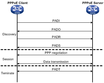
I had 1 hour and 20 minutes wasted trying to figure out the problem with my configuration and it turned out to be that for DHCP request to work the ip address must be on the virtual-template else how would the router know which DHCP pool it'd assign to the client.
Server config
interface Virtual-Template1
ip address 155.1.35.1 255.255.255.0
no peer default ip address
ppp authentication chap
bba-group pppoe 1
virtual-template 1
interface FastEthernet0/1.54
encapsulation dot1Q 54
pppoe enable group 1
ip dhcp pool 1
network 155.1.35.0 255.255.255.0
username R3 password 0 CISCO
Client Config
interface Dialer1
ip address dhcp
encapsulation ppp
dialer pool 1
ppp chap hostname R3
ppp chap password 0 CISCO
!
interface FastEthernet0/1
no ip address
duplex auto
speed auto
pppoe enable group global
pppoe-client dial-pool-number 1
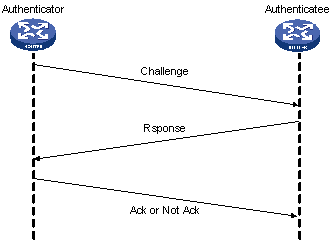
OK now we have to take into perspective when it comes to PPP Authentication one important thing , there are 2 parts of the story ... call them server and client. Server is the device that has the command :
ppp authentication pap <<<<< Authenticate using PAP only
or
ppp authentication chap <<<<< Authenticate using chap only
or
ppp authentication pap chap <<<<<< Try pap if other end refuse try chap
So now since this device requests authentication it must have database for authenticating (username and password) this could be done in config mode
username Device2 password cisco
In other words my PPP session won't come up until i verify that the other end username/password is correct Client is the device that has the command :
ppp pap sent-username Device 2 password cisco
or
ppp chap hostname Device 2
ppp chap password cisco
or
( i make a choice if server is sending pap and chap to refuse pap and accept chap)
ppp pap refuse <<<<<<<<<< When server requests pap authentication i refuse it hence server will offer me chap to do this the server must be having the command ppp authentication pap chap
In other words my PPP session won't come up until i provide correct username/password to the remote device Note : we can make both devices act as server/client and in this way we require mutual authentication :) but always keep in mind the above points when configuring authentication
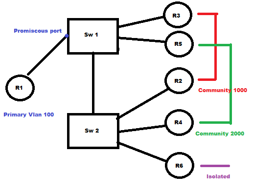
So today i was working on using private vlans and it's such an easy topic but just had many tricks when it comes to configuring it , in the above task we want R1 to be able to ping all routers since its in the primary vlan and its port is promiscous port.
Think of private Vlan as subdividing your vlan into several small vlans in the design above we have sub vlans 1000 and 2000 and isolated vlan 3000
Note that trunking is allowed of course between SW1 and SW2 but let's get down to the configuration because this is the most confusing part. Let's divide the configuration process to 3 parts.
Part 1
Defining VLANS
This should be applied on switch 1 and switch 2
vlan 100
private-vlan primary
!
vlan 1000
private-vlan community
!
vlan 2000
private-vlan community
!
vlan 3000
private-vlan isolated
!
Vlan 100
private-vlan association 1000,2000,3000 <<<<< Take care we must define VLAN association for the primary vlan and also command won't be accepted before you create vlan 1000 and 2000
Part 2
Applying configuration to community and isolated devices.
On switch 2
interface FastEthernet0/2 <<< R2
switchport private-vlan host-association 100 1000 <<<<<< Associate primary vlan to community vlan think of it as a device
switchport mode private-vlan host that has access to 2 vlans :)
!
!
interface FastEthernet0/4 <<< R4
switchport private-vlan host-association 100 2000
switchport mode private-vlan host
!
interface FastEthernet0/6 <<< R6
switchport private-vlan host-association 100 3000
switchport mode private-vlan host <<<<<<< Note isolated vlan don't have special config other than the isolated command in vlan definition
On switch 1
interface FastEthernet0/3
switchport private-vlan host-association 100 1000
switchport mode private-vlan host
!
interface FastEthernet0/5
switchport private-vlan host-association 100 2000
switchport mode private-vlan host
Part 3
Applying configuration to promiscous port On switch 1
interface FastEthernet0/1
switchport private-vlan mapping 100 1000,2000,3000 <<<<< mapping (primary vlan) add (vlan list)
switchport mode private-vlan promiscuous
Verification Using only R2 for verification but to verify you should ping R1 to all devices and each community seperatly
R2#ping 100.0.0.4 <<<< R4
Type escape sequence to abort.
Sending 5, 100-byte ICMP Echos to 100.0.0.4, timeout is 2 seconds:
...
Success rate is 0 percent (0/3)
R2#ping 100.0.0.3 <<<<<<< R3
Type escape sequence to abort.
Sending 5, 100-byte ICMP Echos to 100.0.0.3, timeout is 2 seconds:
.!!!!
Success rate is 80 percent (4/5), round-trip min/avg/max = 1/1/4 ms
R2#ping 100.0.0.1 <<<<<< R1
Type escape sequence to abort.
Sending 5, 100-byte ICMP Echos to 100.0.0.1, timeout is 2 seconds:
!!!!!
Success rate is 100 percent (5/5), round-trip min/avg/max = 1/2/4 ms
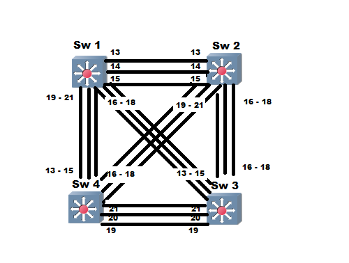
Ok so this point specifically has been causing me alot of headache for the past 2 hours and thank God i was able to figure out how it works , am writing it here because i know very well i will forget it after 1 hour from now. So here's the catch how does a switch choose a root port it all cuts down to the below specific 4 tie breakers.
– Port with the lowest accumulated path cost based on BW [ include cost to root + interface cost ]
– Lowest next hop bridge ID to the root bridge [ bridge ID here stands for designated switch (priority + MAC address)]
– Lowest port priority (1B and is 128 by default) [ port priority of neighbor switch - in most cases root switch]
– Lowest port ID (1B)
So now if i have a topology for MST instance 1 ... me h ... what is MST instance 1 , MST is a sentence of spanning tree where a set of Vlans is associated to 1 STP instance so i'll focus here on MST 1 and by the way below is the configuration i used for MST for memorizing
On Sw1
spanning-tree mode mst
spanning-tree mst configuration
instance 1 vlan 1-100
instance 2 vlan 101 - 200
instance 3 vlan 201 - 1055
exit
spanning-tree mst 1 root primary
Ok now just close your eyes and imagine woooosh spanning tree MST 1 all working with switch 1 working fine let's check switch 2 mst 1 results
Rack1SW2-basicIP#show spanning-tree mst 1
##### MST1 vlans mapped: 1-100
Bridge address 001b.0c7c.a200 priority 28673 (28672 sysid 1)
Root address 001b.2aa7.8200 priority 24577 (24576 sysid 1)
port Fa0/13 cost 200000 rem hops 19
Interface Role Sts Cost Prio.Nbr Type
---------------- ---- --- --------- -------- --------------------------------
Fa0/13 Root FWD 200000 128.15 P2p
Fa0/14 Altn BLK 200000 128.16 P2p
Fa0/15 Altn BLK 200000 128.17 P2p
Fa0/16 Altn BLK 200000 128.18 P2p
Fa0/17 Altn BLK 200000 128.19 P2p
Fa0/18 Altn BLK 200000 128.20 P2p
Fa0/19 Desg FWD 200000 128.21 P2p
Fa0/20 Desg FWD 200000 128.22 P2p
Fa0/21 Desg FWD 200000 128.23 P2p
Fa0/24 Desg FWD 200000 128.26 P2p
Task: I want port Fa0/19 to be the root port (i.e) layer 2 traffic will move from SW2 through SW3 not through SW1
Now remember the tie breakers what's the first Tie breaker ... yes its the cost
Now the point don't be FOOLED by the costs you see on the above output those are the interface cost , remember well root port is chosen based on the total cost [ include cost to root + interface cost ]
Ok let's now compare between the two interfaces Fa0/19 and Fa0/13 Rack1SW2-basicIP#show spanning-tree interface Fa0/19 cost <<<<<<<<<<<< Interface cost
MST0 200000
MST1 200000
MST2 200000
Rack1SW2-basicIP#show spanning-tree interface Fa0/19 rootcost <<<<<<<< Cost to root
MST0 0
MST1 200000
MST2 0
Fa0/19 cost for MST1 is : 400000
Rack1SW2-basicIP#show spanning-tree interface Fa0/13 rootcost
MST0 0
MST1 0
MST2 200000
Rack1SW2-basicIP#show spanning-tree interface Fa0/13 cost
MST0 200000
MST1 200000
MST2 200000
Fa0/13 cost for MST2 is : 200000 So noting the above output whatever cost value i assign to the interface still there's 20000 cost to the root , so as a workaround we'll higher the interface cost on interfaces connecting to SW1 and then change the cost on ports connecting to SW3 as per below Rack1SW2-basicIP(config)#int range fa0/13 - 15
Rack1SW2-basicIP(config-if-range)#spanning-tree mst 1 cost 300000
Rack1SW2-basicIP(config-if-range)#exit
Rack1SW2-basicIP(config)#int fa0/19
Rack1SW2-basicIP(config-if)#spanning-tree mst 1 cost 100
Rack1SW2-basicIP(config-if)#^Z
Rack1SW2-basicIP#show
*Mar 7 23:43:06.359: %SYS-5-CONFIG_I: Configured from console by console
Rack1SW2-basicIP#show span
Rack1SW2-basicIP#show spanning-tree mst 1
##### MST1 vlans mapped: 1-100
Bridge address 001b.0c7c.a200 priority 28673 (28672 sysid 1)
Root address 001b.2aa7.8200 priority 24577 (24576 sysid 1)
port Fa0/19 cost 200100 rem hops 18 <<<<<<<< Notice best cost is 200100 which is cost of Fa0/19
Interface Role Sts Cost Prio.Nbr Type
---------------- ---- --- --------- -------- --------------------------------
Fa0/13 Altn BLK 300000 128.15 P2p
Fa0/14 Altn BLK 300000 128.16 P2p
Fa0/15 Altn BLK 300000 128.17 P2p
Fa0/16 Altn BLK 200000 128.18 P2p
Fa0/17 Altn BLK 200000 128.19 P2p
Fa0/18 Altn BLK 200000 128.20 P2p
Fa0/19 Root FWD 100 128.21 P2p
Fa0/20 Altn BLK 200000 128.22 P2p
Fa0/21 Altn BLK 200000 128.23 P2p
Fa0/24 Desg LRN 200000 128.26 P2p
Now that we're done with the port-cost part let's move to the priority part , i already explained in a previous blog post that changing priority must be done on the neighbor switch that's because of the designated port ID is being compared .... Now after some research on the problem. I believe its not only the neighbor switch that we should care about ...
Because before we think about using point 3 which is the port priority the switch use as a tie breaker the below.
[ bridge ID here stands for next hop designated switch (priority + MAC address) ]
So in most cases if point 1,2 are matched most probably point 3 will be reached on a switch that has blocked ports and is connected to the root itself , that's why it was logical to impact port priority on neighbor switch not on our switch because tie breaker works on the designated port over the segment. Now to conclude this bullshit and many debates all over the forums , now to conclude if you want to make changes to the spanning tree convergence (i.e make an interface takes a separate role than the one it already had simply issue the below command on both interfaces the one that's root and the one that's not
show
First check the total cost to root between both interfaces equal or not ?
if equal
Check the designated bridge priority fied
if equal
Check designated bridge MAC address
if equal
Check designated port ID priority
if equal
Switch will choose the least port ID number
Timers: You actually don't need to set timers on all switches in your LAN environment you need to have it set only on the root switch and the rest of switches will inherit those parameters ;)
Configuring router to send BPDU to switch so you can test BPDU guard and BPDU filter.
(conf-t)
bridge 1 protocol iee
int fa0/1
bridge-group 1
Now for the router to start sending BPDU's remember you need to shut/unshut interface
Rack1R4-basicIP#show span 1
Bridge group 1 is executing the ieee compatible Spanning Tree protocol
Bridge Identifier has priority 32768, address 001c.587d.c001
Configured hello time 2, max age 20, forward delay 15
Current root has priority 24577, address 001b.2aa7.8200
Root port is 5 (FastEthernet0/1), cost of root path is 38
Topology change flag not set, detected flag not set
Number of topology changes 3 last change occurred 00:02:21 ago
Times: hold 1, topology change 35, notification 2
hello 2, max age 20, forward delay 15
Timers: hello 0, topology change 0, notification 0, aging 300
Port 5 (FastEthernet0/1) of Bridge group 1 is forwarding
Port path cost 19, Port priority 128, Port Identifier 128.5.
Designated root has priority 24577, address 001b.2aa7.8200
Designated bridge has priority 28673, address 0026.51e6.9780
Designated port id is 128.6, designated path cost 19
Timers: message age 7, forward delay 0, hold 0
Number of transitions to forwarding state: 2
BPDU: sent 1, received 140 <<<<<<<<<<<<<<<<<<<<<<<<<<<<<<<<<< 1 BPDU sent
BPDU Filter and BPDU guard
BPDU guard simply shuts the port and put it in err-disable mode once a bpdu is received note that both modes need portfast as well to be enabled on interface
BPDU Filter : when recieve BPDU on a portfast enabled interface (i call it stupidity) it disables port fast !
Rack1SW4-basicIP(config)#spanning-tree portfast bpdufilter default
Rack1SW4-basicIP#show spanning-tree interface FastEthernet0/4 portfast
VLAN0001 disabled <<<<<<<<<<<<<<<<<<< After sending BPDU from adjacent router
ERR-Disable recovery
If you don't want the hassle of shutting and unshut ports when they go into err-disable there's this sweet err-disable recovery command
Rack1SW4-basicIP(config)#errdisable recovery cause bpduguard
Rack1SW4-basicIP(config)#errdisable recovery interval 120 <<<<<<<<<<< 120 seconds to recover
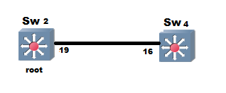
I noticed that problem while using port-priority to tweak spanning tree convergence on one segment and that on my local switch if i change the priority of the port that has no effect on my switch , i have to change the port priority on the designated port switch for it to work , not sure of details but seems that the root port choice is based on port priority advertised from designated switch (lowest designated port priority)
Since in the below example the designated port is on the neighbor switch , changes i do on my switchport won't make any reflection to the tie breaker role , the only thing that would work is changing port priority on my neighbor switch which is the designated switch
Example :
Here as per previous post the lowest ID interface wins and become root port so we have something like this and we want to tweak port priority value on Fa0/16 on SW4 interface so as to choose another port as root port (i.e) Fa0/17 which is currently in blocked state
Rack1SW4-basicIP#debug span even
Spanning Tree event debugging is on
Rack1SW4-basicIP#conf t
Enter configuration commands, one per line. End with CNTL/Z.
Rack1SW4-basicIP(config)#int fa0/16
Rack1SW4-basicIP(config-if)#spanning-tree port-priority ? <<<<<<<<< Default is 180
<0-240> port priority in increments of 16
Rack1SW4-basicIP(config-if)#spanning-tree port-priority 240
Rack1SW4-basicIP(config-if)#
6d18h: set portid: VLAN0001 Fa0/16: new port id F012
6d18h: set portid: VLAN0005 Fa0/16: new port id F012
6d18h: set portid: VLAN0007 Fa0/16: new port id F012
Rack1SW4-basicIP(config-if)#^Z
Rack1SW4-basicIP#show spa
6d18h: %SYS-5-CONFIG_I: Configured from console by console
Rack1SW4-basicIP#show span
Rack1SW4-basicIP#show spanning-tree bloc
Rack1SW4-basicIP#show spanning-tree blockedports
Name Blocked Interfaces List
-------------------- ------------------------------------
VLAN0001 Fa0/17, Fa0/18 <<<<<<<<<<<<<<<<<<< Still in blocked state
VLAN0005 Fa0/17, Fa0/18
VLAN0007 Fa0/17, Fa0/18
VLAN0008 Fa0/17, Fa0/18
VLAN0009 Fa0/17, Fa0/18
***** As you can see nothing changed here , now next let's change the priority on the neighbor switch Fa 0/19
Rack1SW2-basicIP(config)#int fa0/19
Rack1SW2-basicIP(config-if)#spanning-tree port-priority 240
Rack1SW2-basicIP(config-if)#
*Mar 7 18:21:04.619: set portid: VLAN0001 Fa0/19: new port id F015
*Mar 7 18:21:04.619: set portid: VLAN0005 Fa0/19: new port id F015
*Mar 7 18:21:04.619: set portid: VLAN0007 Fa0/19: new port id F015
*Mar 7 18:21:04.619: set portid: VLAN0008 Fa0/19: new port id F015
--- Notice how topology change is reflected on SW4 and yes now we have the correct port blocked
Rack1SW4-basicIP#show spanning-tree blockedports
6d18h: STP: VLAN0001 new root port Fa0/17, cost 19
6d18h: STP: VLAN0001 Fa0/17 -> listening
6d18h: STP: VLAN0005 new root port Fa0/17, cost 19
6d18h: STP: VLAN0005 Fa0/17 -> listening
6d18h: STP: VLAN0007 new root port Fa0/17, cost 19
6d18h: STP: VLAN0007 Fa0/17 -> listening
6d18h: STP: VLAN0008 new root port Fa0/17, cost 19
6d18h: STP: VLAN0008 Fa0/17 -> listening
6d18h: STP: VLAN0009 new root port Fa0/17, cost 19
6d18h: STP: VLAN0009 Fa0/17 -> listening
6d18h: STP: VLAN0010 new root port Fa0/
Rack1SW4-basicIP#show spanning-tree blockedports
Rack1SW4-basicIP#show spanning-tree blockedports
Name Blocked Interfaces List
-------------------- ------------------------------------
VLAN0001 Fa0/16, Fa0/18
VLAN0005 Fa0/16, Fa0/18
VLAN0007 Fa0/16, Fa0/18
VLAN0008 Fa0/16, Fa0/18
VLAN0009 Fa0/16, Fa0/18
VLAN0010 Fa0/16, Fa0/18
|


 RSS Feed